+
  • 002a.jpg
  • 光面土工膜2.jpg
  • 光面土工膜3.jpg

Smooth HDPE Geomembranes

Geomembrane paving is completed, should minimize walking on the membrane surface, moving tools, etc., where the geomembrane can cause harm to the object, should not be placed on the membrane or carry walking on the membrane, so as not to cause accidental damage to the membrane.

PRODUCT DETAILS

Purpose of action

Environmental protection engineering: landfill, sewage treatment plant, chemical wastewater pond, power plant regulating pond, industrial/medical waste landfill, ash field, evaporation pond seepage control.

Petrochemical: petrochemical refinery tanks, oil well sludge ponds, chemical reaction ponds, sedimentation ponds, tailings dams, bottom lining, secondary lining seepage control. Secondary lining seepage control.

Chemical and mining industry: the bottom lining seepage control of ash field, red mud pile, heap leaching pool, dissolving pool, sedimentation pool, tailings dam.

Aquaculture: lining of aquaculture ponds, fish ponds, shrimp ponds, seepage control of sea cucumber rings and slopes.

Construction engineering: subway, underground garage, roof garden, sewage pipe, seepage control of dredging culvert.

Agriculture, forestry and animal husbandry: seepage control of reservoirs, cisterns, drinking water pools and irrigation systems.

Salt chemical industry: seepage control of salt crystallization ponds, brine ponds and salt membranes.

Construction technology

Geomembrane paving is completed, should minimize walking on the membrane surface, moving tools, etc., where the geomembrane can cause harm to the object, should not be placed on the membrane or carry walking on the membrane, so as not to cause accidental damage to the membrane. When laying geomembrane, we should strive to weld less, under the premise of ensuring the quality of welding, and try to save raw materials. The lap width of the joints between the membrane and the membrane is generally not less than 10cm, and the weld seams are usually arranged parallel to the larger slope, i.e. along the direction of the slope.


Technical indicators

Ordinary high-density polyethylene geomembrane (GB/T 17643 2011 GH-1 type technical indicators)

Item Indicator
Thickness  m m 0.30 0.50 0.75 1.00 1.25 1.50 2.00 2.50 3.00
densities g/cm³ ≥0.940
Tensile yield strength (longitudinal and transverse) N/mm ≥4 ≥7 ≥10 ≥13 ≥16 ≥20 ≥26 ≥33 ≥40
Tensile breaking strength (longitudinal and transverse) N/mm ≥6 ≥10 ≥15 ≥20 ≥25 ≥30 ≥40 ≥50 ≥60
Yield elongation (longitudinal and transverse) %       ≥11
Elongation at break (longitudinal and transverse) % ≥600
Right angle tearing load (longitudinal and transverse) N ≥34 ≥56 ≥84 ≥115 ≥140 ≥170 ≥225 ≥280 ≥340
Puncture strength N ≥72 ≥120 ≥180 ≥240 ≥300 ≥360 ≥480 ≥600 ≥720
Carbon black content % 2.0-3.0
Carbon Black Dispersibility No more than 1 out of 10 data at level 3, not allowed at levels 4 and 5
Atmospheric pressure oxidation induction time (OIT)min ≥60
Low temperature impact embrittlement properties pass
water vapor permeability coefficient g ·cm/(cm2 · s ·Pa) ≤1.0×10⁻¹³
Dimensional stability % ±2.0


Environmental protection high-density polyethylene geomembrane "GB/T 17643-2011 GH-2S type technical indexes

Item Indicator
thicknesses mm 0.75 1.00 1.25 1.50 2.00 2.50 3.00
Densities g/cm³ ≥0.940
Tensile yield strength (longitudinal and transverse) N/mm ≥11 ≥15 ≥18 ≥22 ≥29 ≥37 ≥44
Tensile breaking strength (longitudinal and transverse) N/mm ≥20 ≥27 ≥33 ≥40 ≥53 ≥67 ≥80
Yield elongation (longitudinal and transverse) % ≥12
Elongation at break (longitudinal and transverse) % ≥700
Right angle tearing load (longitudinal and transverse) N ≥93 ≥125 ≥160 ≥190 ≥250 ≥315 ≥375
puncture strength N ≥240 ≥320 ≥400 ≥480 ≥640 ≥800 ≥960
Stress cracking under tensile load   ≥300
Carbon black content % 2.0~3.0
Carbon Black Dispersibility No more than 1 out of 10 data at level 3, not allowed at levels 4 and 5
Atmospheric pressure oxidation induction time (OIT)min Atmospheric pressure oxidation induction time ≥ 100
High pressure oxidation induction time ≥ 400
85°C heat aging % ≥55
anti-ultraviolet ≥50


Glossy HDPE geomembrane for landfill "CJ/T 234-2006 Technical Specification" (equivalent to US GRI-GM13 standard)

Item Indicator
thicknesses mm 0.75 1.00 1.25 1.50 2.00 2.50 3.00
Densities g/cm³ ≥0.939
Tensile yield strength (longitudinal and transverse) N/mm ≥11 ≥15 ≥18 ≥22 ≥29 ≥37 ≥44
Tensile breaking strength (longitudinal and transverse) N/mm ≥20 ≥27 ≥33 ≥40 ≥53 ≥67 ≥80
Yield elongation (longitudinal and transverse) % ≥12
Elongation at break (longitudinal and transverse) % ≥700
Right angle tearing load (longitudinal and transverse) N ≥93 ≥125 ≥156 ≥187 ≥249 ≥311 ≥374
puncture strength N ≥240 ≥320 ≥400 ≥480 ≥640 ≥800 ≥960
Resistant to environmental stress cracking ≥300
Carbon black content % 2.0~3.0
Carbon Black Dispersibility No more than 1 out of 10 data at level 3, not allowed at levels 4 and 5
Atmospheric pressure oxidation induction time (OIT)min Atmospheric pressure oxidation induction time ≥ 100
High pressure oxidation induction time ≥ 400
85°C heat aging % ≥55
anti-ultraviolet ≥50

光面土工膜
Smooth HDPE Geomembranes

PROJECT CASES
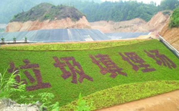
Landfill
Landfill

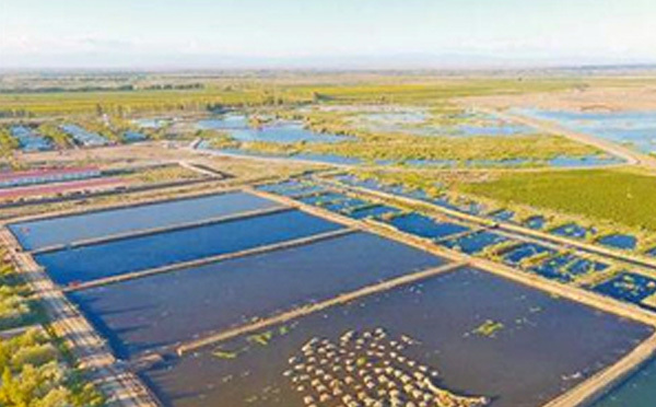
Agriculture/Aquaculture

Agriculture/Aquaculture

Artificial lake/wetland park
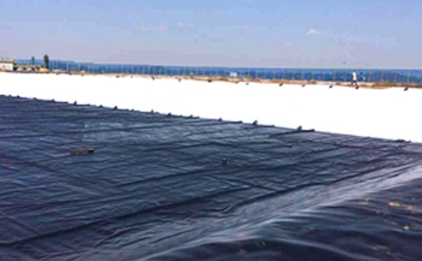
Artificial lake/wetland park

Chemical/Solid and Hazardous Waste Containment
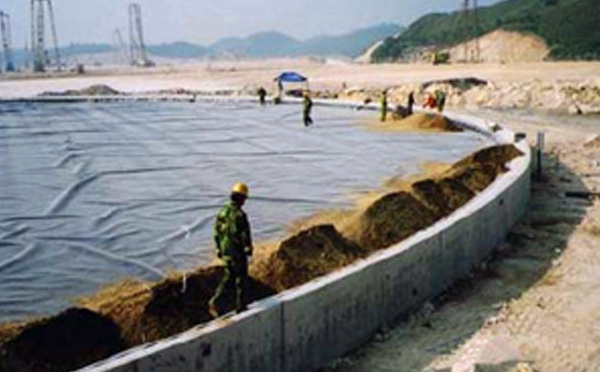
Chemical/Solid and Hazardous Waste Containment

Refinery/tank containment
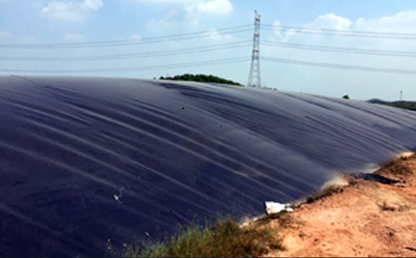
Refinery/tank containment

Conditioning tanks/biogas digesters

Conditioning tanks/biogas digesters

TESTING EQUIPMENT

Testing Equipment8

Testing Equipment8

Testing Equipment7

Testing Equipment7

Testing Equipment6

Testing Equipment6

Testing Equipment5

Testing Equipment5

Testing Equipment4

Testing Equipment4

Testing Equipment3

Testing Equipment3

Testing Equipment2

Testing Equipment2

Testing Equipment

Testing Equipment

FAQ

GET A FREE QUOTE